Limit Switches for Astro-Physics AP1200
This page shows one way to add limit switches to an equatorial mount. This implementation is customized for Astro-Physics mounts, specifically the AP1200, but the hardware and software will work for any mount for which you have access to a point that rotates in right ascension but not in declination.
Well, if I trusted the equipment to work all of the time, I wouldn't. But I've spent too many years working with hardware, firmware, and software and I just don't trust it.
My AP1200 mount will continue tracking until something tells it to stop. That "something" is one or more complex programs running under a complex operating system on a complex computer communicating to the mount over consumer grade USB cables and hubs. If any of that fails, the mount does not stop tracking.
I want a simple and reliable failsafe.
Andy, at ADGSoftware, has a great little program called Mount Watcher that monitors the mount's position via the ASCOM driver and commands it to stop tracking if it goes a specified distance past meridian. The program supports a hardware watchdog that will stop the mount if the application stops sending it keep-alives. This is a great solution to the "computer died and nothing is there to stop tracking" problem. Check it out; it's easier and cheaper than my solution!
AstroPhysics sells APCC which includes a "Safety countdown timer to protect from COM loss". I assume that it, too, does some sort of keep-alive in the GTOCP3 or GTOCP4 controller to detect that it is no longer talking to APCC and stops tracking if that happens. This solution, though expensive if you don't already have APCC, would be something that is actually supported by the mount manufacturer.
If you are still reading at this point, I guess you are interested in what I did! So let's get to it.
My goals for this project are:
Yes, the arduino is hardware that runs microcode and an application program. It is, however, much less complex than a PC running and OS and many applications. And the program that I made is a very simple program. Maybe I don't totally trust it, but I do trust it more than my PC!
An Arduino microcontroller monitors a 3-axis accelerometer and holds a relay closed as long as the rotation angle is within a set range.
The accelerometer gives the acceleration due to gravity in all three axes. Using these values it is simple to compute the roll, pitch, and yaw angles. I mount the accelerometer so that its X-axis is close to the mount's right ascension axis. Thus the roll angle changes with right ascension and I can ignore pitch and yaw.
A normally open relay interrupts the power to the mount. The Arduino also gets its power from this source. While the current roll angle is between the East and West limit angles, the Arduino holds the relay closed, thus powering the mount. If the angle goes out of those limits, the Arduino opens the relay, removing power from the mount. Manual recovery is necessary.
A button and three LEDs allow the user (me!) to set the East and West limits. Those limits are stored in EEPROM so they will automatically be re-used unless the user enters the limit setting procedure, described later.
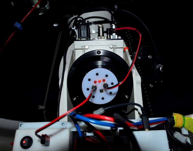
I mount the device in the polar alignment scope area, giving it perfect alignment with the RA axis. Though I bought a PAS with the mount, I have never really used it since the daytime alignment procedure makes it so easy to get an alignment that is plenty good for visual and PHD2 makes drift alignment quick and easy. I did use one part of the PAS adapter in the housing assembly, which I'll describe later.
Here is a list of the parts. I have identified the actual model I used where it matters. If you use a different part, you may have to modify the code. For example, there are many accelerometers available; if you don't use the Adafruit MMA8451, you will need a different library and interface to it.
I had to include the DC-DC Step-Down module because I often run the mount at 15V. The Arduino Pro Micro operates best on 7-12V input.
OK, so I started to draw a schematic in Visio, but decided that I needed to learn Fritzing since it seems to be the tool of choice for Arduino projects. So, here is the Fritzing layout on a bread board.
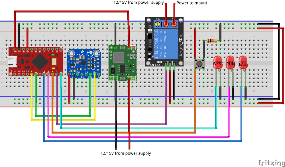
The power for the Arduino circuit is tapped off of the power that would normally go to the mount. As mentioned earlier, I used a step-down module to account for the 15V that I normally use to run the AP1200. 12 to 15 volts enter the step-down module (green component in the center of the diagram) from the bottom. The 7VDC regulated output goes to the ground bus and to the power input of the Arduino Pro Micro (RAW pin). The Arduino GND pin is fed from the ground bus and the Arduino's VCC pin feeds 5VDC regulated current to the rest of the devices.
The MMA8451 accelerometer comminicates with the Arduino using I2C. Arduino pin 2 connects to the MMA8451's SDA pin and Arduino pin 3 to SCL.
The relay module is controlled by Arduino pin 8 as a straight digital output. For the relay output, the mount's power supply is connected to the COMMON terminal and the NORMALLY OPEN terminal feeds that power to the mount. When the relay opens, the mount loses power and stops.
The button is the sole user input for the device. It uses a pull-down resistor to allow a high signal on Arduino pin 7. Pressing and/or holding the button at different times commands the Arduino to do different things.
The three LEDS indicate the status of the circuit by flashing or illuminating solid. All three LEDs are controlled by PCM, set at the lowest brightness value; I probably should have put a resistor in series with them. The center LED is the RUN LED and is connected to Arduino pin 6. The left LED is West on pin 9 and the right LED is East on pin 5.
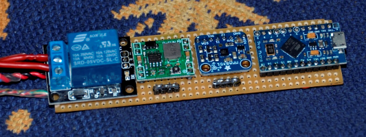
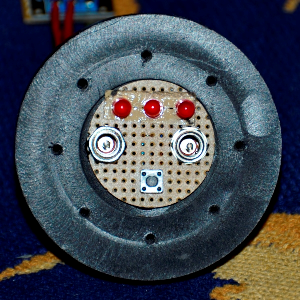
I built the control circuit on a prototype board trimmed down to fit in the AP1200's polar axis. I do not solder very well and am not going to show you the back of this board! It's messy, but it works. The larger black and red wires are the power to the step-down module. The smaller twisted wires are the input/output for the button and LEDs. The two large red wires are the mount power, controlled by the relay.
The Arduino is on the end so that I can still plug a USB up to it if I need to reprogram it. So far, I haven't found any bugs. But this is my first Arduino project and I'm sure I'll eventually have to fix or change something.
The user interface board contains the three LEDs, the button, and 12/15VDC power in and out. The mount's power supply connects to the left coax power connector and the right connector goes to the mount itself. The wires connecting the UI board to the control board have plug-in connectors so I can separate them if necessary.
The code is a bit long at a little over 400 lines and, being my first Arduino project, is probably not your typical sketch code. Trading defensive coding for fitting functionality in very limited memory with very limited inputs and outputs is hard to get used to!
Since I used the Adafruit sensor, I used their Sensor and MM8541 libraries. The EEPROM library lets me store the West and East limits so I can set them once and forget about them in most cases. I also use the non-local goto to control reinitialization and restart on a button hold. This works well and is perfect for the rarely used setjmp and longjmp calls. This is probably the third time in my 30 years of programing I've legitimately used these functions.
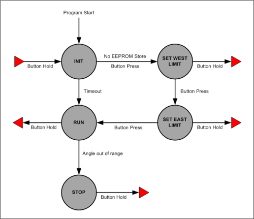
The code is a simple state machine. Transitions are controlled by the button and by the accelerometer values.
I have the advantage of a decently equipped workshop, particularly a milling machine that works well with both metal and plastic. So I'm always looking for a good excuse to spend some time out there! Though my implementation mounts in the polar alignment scope location, it really doesn't matter where you put it as long as it rotates with the right ascension axis. I'm probably going to make another one for a friend and just put it in a box that can be attached to the mount housing with Velcro.
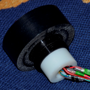
The photo on the right shows the part that holds the LEDs, button, and power connectors. The
middle of this part (you can see the threads) is from the Astro-Physics adapter that allows the
Losmandy polar scope to fit in the AP1200. I machined the large black plastic disc to hold the
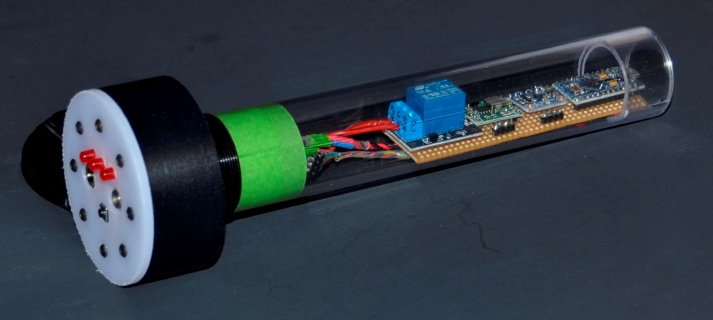
user interface circuit board and the smaller white cylinder to hold a polycarbonate tube in which
the control circuit board rests. 3M very high bond double-sided tape holds the threaded part to
the black plastic disk and the white cylinder is threaded into its other end. The polycarbonate
tube, shown in the picture of the complete assembly earlier in the page, is simply a friction fit
on the white cylinder.
Operation is simple. The Arduino boots when the mount's power supply is plugged in to the left coax power connector. At this point, the relay is closed providing power to the mount and the RUN LED begins flashing for 5 seconds. You have two options:
If you enter setup mode, the WEST LED will start flashing. This is your cue to rotate the mount in RA to the furthest position West that you want the mount to go. Then you press the button again and the EAST LED starts flashing. Rotate the RA axis to the East limit and press the button one more time. The RUN light flashes and limits are suppressed for 5 seconds so you can rotate the RA axis away from the East limit and avoid an immediate limit violation. These limits that you set are automatically stored in EEPROM and available for the next session.
In RUN mode, the RUN LED is illuminated constantly and the Arduino enters a forever loop where it queries the accelerometer and calculates the current roll angle. If that roll angle is less than the West limit or greater than the East limit, the relay is opened and the mount loses power.
At any time, you can hold the button down for 2 or more seconds to restart the device. This is how you recover from a limit switch violation—just slew the mount Eastward during the first 5 seconds after restart.
The animation on the right shows the limit switch engaging and stopping the mount as I hold down the West button at a 64X sideral slew rate. The LED switches from the center RUN LED to the left WEST LED when the limit is reached. If you look closely, you can see that the keypad display shut off at the same time the mount stopped moving.
As you can see from the description of the device, you only get to store a single limit for each direction. It doesn't matter what declination that the mount is pointing; you still only get one limit. When pointing at low declination (from the Northern hemisphere) this means that you may stop long before the telescope or camera comes anywhere near the mount or pieir. In fact, for many declinations the mount can easily rotate 360° without contact. Whether your cables can handle 360° is a different question! This works fine for me; I typically image the same object night after night and I can simply set the limits for the declination that I know I will be in all night long.
My code is for Northern hemisphere usage. I think you will have to reverse the current roll angle comparisons to use it in the Southern hemisphere.